How to Choose a Three Row Roller Slewing Bearing in 2026

Time:2026-11-03 Author:Isabella
0%

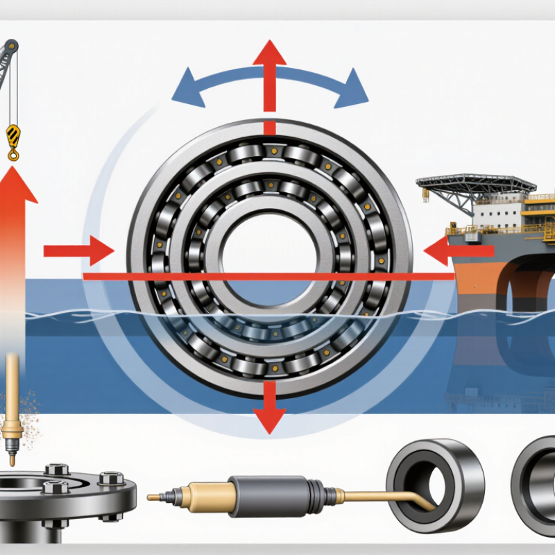
Choosing a Three-Row Roller Slewing Bearing in 2026 begins with the machine, not the catalog. A crane boom, excavator upper structure, and offshore platform impose different combinations of axial load, radial force, and overturning moment. Duty cycle matters too. A bearing that handles a brief peak may not suit repeated shock loading or continuous rotation.

Bearing analyst Tedric A. Harris is known for rigorous, load-based bearing analysis. A practical paraphrase of that approach is: “Choose for the real load path, not the headline capacity.” That distinction is easy to miss. Three roller rows can support substantial loads, but the complete assembly still depends on raceway geometry, gear forces, mounting-flange stiffness, bolt patterns, lubrication, and sealing. Look closely at the machine’s actual operating data. A spreadsheet estimate may not capture a sudden stop or a flexible support frame.

Details count. Think of uneven bolt tightening, grease channels, and abrasive dust at the seal lip. These can influence service life as much as a catalog rating. This guide explains how to compare load capacity, dimensions, materials, accuracy, and maintenance needs before selecting a bearing. It also flags a common uncertainty: early load estimates are often incomplete. Verify assumptions with the machine designer and bearing supplier, then confirm the proposed bearing against the real installation and operating conditions.
How to Choose a Three Row Roller Slewing Bearing in 2026

Define the Duty Cycle: Axial Load, Radial Load, and Tilting Moment

For a three-row roller slewing bearing, define the duty cycle before comparing load ratings. Record axial force, radial force, and tilting moment at the bearing interface. Include normal operation, starts and stops, reversals, and occasional shocks. Peak load matters. So does repetition.

A suspended load may create a large tilting moment when it sits far from the rotation axis. Measure that offset, rather than estimating from the load alone. Radial force can also change direction as the machine swings. Note how often each load combination occurs and how long it lasts. A single maximum-load figure can hide the actual working pattern. It is an easy mistake.

Use these operating details to check the bearing’s load curves and expected service life. Also confirm that the mounting structure stays sufficiently stiff; a flexible support can distort load distribution. If the machine runs in short, frequent movements, describe that clearly in the calculation. Average load alone may understate fatigue exposure. Share the assumptions with a qualified bearing engineer, especially when shock loads or uncertain load sharing are involved. A tidy spreadsheet is useful, but it cannot repair weak input data.

Match Three Roller Rows to Combined Load Requirements

A three-row roller slewing bearing suits applications where axial force, radial force, and overturning moment act together. Separate roller rows typically carry different load directions: the upper and lower rows handle axial loads, while the middle row supports radial loads. This arrangement can provide high stiffness for excavators, cranes, and other heavy rotating structures. It is not automatically the best choice. Its size, mass, and installation demands may exceed what a lighter-duty machine needs.

Start with the real load cases, not a single headline capacity. Record operating loads, shock events, rotation speed, duty cycle, and the largest overturning moment. A crane slewing through a gust, for example, may see a very different load pattern from one rotating steadily indoors. Check the supporting structure, bolt pattern, and mounting-face flatness too; poor support can distort load sharing between rows. A calculation is only as reliable as its inputs. Revisit assumptions with the bearing supplier or a qualified engineer, especially when loads change during operation.

Tips: Keep a short load-case table, including peak and normal conditions. Confirm lubrication access and seal protection for the actual environment. Leave room for inspection. Small details matter, though they are easy to miss.

Check Static Capacity Using ISO 76 Basic Static Load Ratings

How to Choose a Three Row Roller Slewing Bearing in 2026

For a three-row roller slewing bearing, static capacity starts with the actual load case, not the largest number on a data sheet. Record axial force, radial force, and overturning moment at the bearing interface. Include parked loads, installation forces, and brief shocks; a slowly rotating crane can still face a severe static case. Small margins matter.

ISO 76:2006, including Amendment 1:2017, sets a calculated contact-stress basis of 4,000 MPa for roller-bearing basic static load ratings. That figure is a rating basis, not a safe working load. Compare the calculated equivalent static load, P₀, with the bearing’s C₀ rating and calculate the static safety factor, C₀/P₀. For a three-row unit, use the supplier’s prescribed load-distribution method; do not add row ratings blindly. That shortcut can hide uneven sharing.

Check the required safety factor against duty, load uncertainty, and the consequences of permanent indentation. Confirm which row carries the highest load, especially when a tall boom creates a large overturning moment. Review mounting flatness and support stiffness too: a distorted seat can concentrate contact loads. Revisit assumptions after field measurements; calculated loads are sometimes tidier than real starts and stops.

Estimate L10 Life with ISO 281: 90% Reliability, Roller Exponent 10/3

For a three-row roller slewing bearing, estimate life from the actual load mix: axial force, radial force, and overturning moment. ISO 281:2007 defines basic rating life, L10, at 90% reliability. For rollers, use L10 = (C/P)^(10/3) million revolutions, where C is the basic dynamic load rating and P is the equivalent dynamic load. The exponent matters: small changes in load can sharply change the estimate.

For example, if C/P equals 2, the calculation gives about 10.1 million revolutions. That is a rating-life estimate, not a service-life guarantee. ISO 281’s basic calculation does not capture every real operating condition. Slewing drives may turn slowly, reverse direction, or move through short oscillations. Uneven support, lubrication quality, contamination, and shock loads can also alter bearing performance. A load spectrum from the actual duty cycle is more useful than one peak-load value. I would treat the result as a starting point, not a final answer.

Tips: Confirm the bearing’s rated loads and equivalent-load method with the supplier. Check mounting flatness and bolt preload; small errors matter. Record operating hours and movement cycles, then review the estimate against inspection findings.

Three-Row Roller Slewing Bearing: ISO 281 L10 Life Estimate

Illustrative basic rating life at 90% reliability for roller bearings, using the ISO 281 exponent of 10/3. Life decreases as the equivalent dynamic load P increases relative to the basic dynamic load rating C.

Calculation: L10 = (C / P)10/3 million revolutions. Estimates assume constant equivalent dynamic load and standard rating conditions; actual slewing-bearing life can vary with load spectrum, oscillation, lubrication, contamination, and installation.

Verify Gear, Bolt, Lubrication, and Clearance Requirements for the Application

How to Choose a Three Row Roller Slewing Bearing in 2026

A three-row roller slewing bearing can carry substantial axial, radial, and overturning loads, but selection depends on the complete installation. Start with operating loads, rotation speed, duty cycle, and shock exposure. Then verify the gear type and tooth geometry against the pinion. Check module, pressure angle, and allowable backlash in the assembly drawing. Poor meshing may cause noise, uneven wear, or localized tooth stress. Small errors matter.

Confirm bolt size, grade, quantity, and tightening method against the specified mounting arrangement. The support structure must also be flat and stiff; a distorted seat can affect raceway clearance and load distribution. Review the lubricant, delivery points, and relubrication interval for the actual duty and environment. Grease should reach each specified port, not just the easiest one. Check sealing and contamination risks. Clearance matters.

Tips: Measure mounting-face flatness and gear backlash during installation. Record bolt torque and clearance readings. If a drawing leaves a value unclear, pause and request written confirmation. Guessing is tempting, but costly. Recheck after initial operation, since settling can change readings.

How to Choose a Three Row Roller Slewing Bearing in 2026 — Verify Gear, Bolt, Lubrication, and Clearance Requirements for the Application

Selection Dimension What to Verify Application Check Information to Record
Load conditions Three-row roller designs use separate roller raceways to carry axial, radial, and overturning loads. Confirm the combined load cases against the bearing’s rated capacity and service-life requirements. Include the maximum operating load, load direction, moment, shock or impact, and relevant duty cycle. Do not select from static load alone when the bearing rotates in service. Axial load, radial load, overturning moment, load combinations, operating hours, and required life.
Gear configuration Check whether the application requires an internal gear, external gear, or an un-geared bearing. Confirm module or diametral pitch, tooth count, pressure angle, gear accuracy, and pinion compatibility from the design drawing. Verify pinion alignment, center distance, tooth contact, backlash, rotation direction, and available space. Set backlash to the applicable drawing or engineering specification; there is no universal value for every assembly. Gear type, tooth data, pinion details, specified backlash, alignment method, and inspection results.
Mounting bolts and joint Confirm bolt diameter, thread, quantity, property class, engagement, washers, and mounting-hole geometry. Check the bearing and support structure requirements together. Use the specified tightening sequence and torque or tension procedure. Required preload depends on the joint design, bolt condition, friction, and bearing instructions; do not apply a generic torque value. Bolt specification, tightening method, target torque or preload, sequence, and support-surface inspection.
Mounting structure Check that the upper and lower support structures have adequate stiffness and meet the bearing maker’s flatness and surface-condition requirements. Inspect for burrs, paint buildup, debris, soft spots, and local distortion. A non-flat or flexible structure can deform the bearing and affect raceway load distribution and running behavior. Support material and thickness, flatness measurement, surface preparation, and any reinforcement details.
Lubrication Identify the specified grease type, consistency, compatibility, lubrication points, and relubrication method for the raceways and gear teeth. Raceway and gear lubrication requirements may differ. Follow the bearing-specific lubrication schedule and quantity. Consider operating speed, temperature, contamination, water exposure, and duty cycle. Do not mix greases unless compatibility has been confirmed. Grease specification, initial fill, relubrication interval, applied quantity, and service environment.
Clearance and runout Confirm the specified initial internal clearance or preload condition, axial and radial movement limits, and applicable runout tolerances. Measure according to the approved procedure and at the specified points. Record readings before and after mounting where required; mounting distortion and load can change measured movement. Clearance type, measurement locations, readings, runout values, measurement conditions, and acceptance limits.
Speed and motion Check allowable rotational speed, oscillation angle, acceleration, and start-stop frequency for the selected bearing and lubrication arrangement. Slow or intermittent rotation can still require frequent lubrication, especially under high loads or in contaminated environments. Confirm the application duty with the bearing supplier or design authority. Maximum speed, average speed, oscillation range, starts per hour, and operating cycle.
Seals and environment Review seal arrangement and protection for dust, water, abrasive particles, temperature, and any washdown or outdoor exposure. Check seal condition during installation and maintenance. Seals reduce contamination ingress but do not remove the need for correct lubrication and inspection. Environmental conditions, seal configuration, contamination risks, and inspection frequency.
Commissioning and maintenance Establish baseline measurements for rotation, noise, temperature, clearance, gear contact, and fastener condition as applicable. Use the equipment maintenance plan and bearing-specific instructions. Investigate changes in noise, vibration, temperature, leakage, gear contact, or measured clearance rather than relying on a single symptom. Baseline readings, inspection schedule, lubrication log, tightening records, and corrective actions.

Selection note: Final dimensions, load ratings, tolerances, bolt tightening values, lubrication quantities, and service intervals must be confirmed against the bearing drawing, application calculations, and the applicable manufacturer instructions.

FAQS

What loads should I record when selecting a three-row roller slewing bearing?

Record axial force, radial force, and tilting moment at the bearing interface. Include normal operation, starts, stops, reversals, and occasional shocks. Peak loads matter.

Why is the suspended load’s offset important?

A load positioned far from the rotation axis can create a large tilting moment. Measure the offset instead of estimating from load weight alone. Easy to miss.

How should I describe the duty cycle?

Note how often each load combination occurs and how long it lasts. Include frequent short movements, not just average load. Fatigue can be understated.

How are the three roller rows typically arranged to carry loads?

The upper and lower rows typically handle axial loads. The middle row supports radial loads. Together, they can manage combined loading and overturning moments.

Is a three-row bearing always the best option for heavy rotating equipment?

No. It may suit cranes, excavators, and similar structures, but its size, mass, and installation needs may exceed a lighter-duty machine’s requirements.

What installation details should I verify?

Check that the mounting structure is flat and stiff. Confirm bolt size, grade, quantity, and tightening method. A distorted seat can affect load sharing.

What should I check between the bearing gear and pinion?

Verify tooth geometry, module, pressure angle, and allowable backlash against the assembly drawing. Poor meshing can cause noise, uneven wear, or concentrated tooth stress.

How can I check lubrication and installation after setup?

Confirm grease reaches every specified port, and review sealing for the operating environment. Record bolt torque, mounting-face flatness, and backlash. Recheck after initial operation; settling can change readings. I would not guess at unclear drawing values.

Conclusion

Choosing a Three-Row Roller Slewing Bearing in 2026 starts with defining the application’s duty cycle. Record the expected axial and radial loads, tilting moment, operating speed, and the frequency and duration of peak loads. The three roller rows support different components of combined loading, so compare the bearing’s configuration and rated capacity with the actual load cases rather than selecting by size alone. Include start-up, stopping, shock, and other demanding operating conditions in the assessment.

Check static capacity using the applicable ISO 76 basic static load ratings, including the effects of combined loads and any required safety margin. For fatigue life, estimate L10 life using ISO 281, which represents 90% reliability under the specified conditions; for roller bearings, use the life exponent of 10/3. Finally, verify that the gear arrangement, mounting bolts, lubrication method, and internal clearance suit the equipment and maintenance plan. A complete review of these factors helps ensure reliable operation and a well-matched bearing selection.


Isabella

Isabella

Isabella is a dedicated marketing professional with a sharp focus on driving brand growth and engagement through strategic content creation. With an extensive background in digital marketing, she combines her passion for storytelling with her keen understanding of industry trends to deliver......