1 / 1
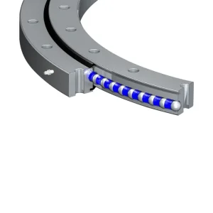
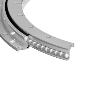
When using worm gears, this is its most prominent feature. The worm gear transmission naturally has one-way self-locking property. When the motor stops, the output flange can reliably lock at the current position, capable of withstanding huge static loads without the need for additional brakes, with a high safety factor.
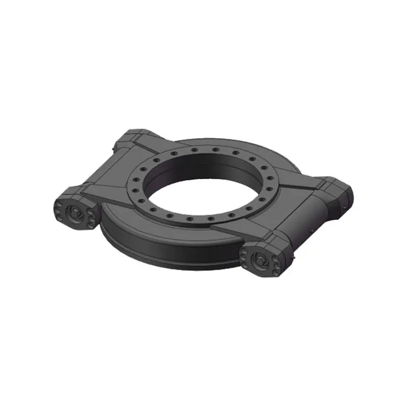
The horizontal motor layout does not occupy the vertical space above the equipment, making the overall design more flat. The motor can be installed sideways, facilitating layout in space-constrained environments.
A single stage of worm gears can achieve a significant reduction ratio (typically from 5:1 to 100:1), thereby providing extremely high output torque within a compact volume.
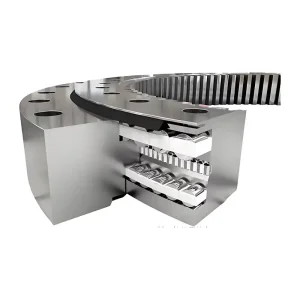
Users do not need to design the drive and support systems separately. They only need to fix the device as a whole, connect the power supply and control lines, reducing R&D and assembly complexity.
As a standardized and mass-produced industrial module, it delivers highly competitive performance for its cost, optimizing total system expenditures.
| Horizontal Slewing Drives Technical Parameters | ||||||||||
|---|---|---|---|---|---|---|---|---|---|---|
| Data Model | Output Torque (kN.m) | Tilting Moment (kN.m) | Holding Torque (kN.m) | Static Axial Load (kN) | Static Radial Load (kN) | Dynamic Axial Load (kN) | Dynamic Radial Load (kN) | Gear Ratio | Tracking Precision | Weight (kg) |
| WSP07 | 1.45 | 13.5 | 10.4 | 133 | 53 | 32 | 28 | 73:1 | ≤ 0.2° | 29 |
| WSP09 | 8 | 35.6 | 28.7 | 578 | 215 | 136 | 115 | 62:1 | ≤ 0.15° | 48.5 |
| WSP12 | 9.5 | 57 | 43 | 760 | 280 | 190 | 148 | 78:1 | ≤ 0.15° | 65 |
| WSP14 | 10.8 | 71.2 | 48 | 960 | 360 | 230 | 200 | 86:1 | ≤ 0.13° | 74 |
| WSP17 | 12.96 | 142.4 | 72.3 | 1166 | 435 | 280 | 231 | 104:1 | ≤ 0.1° | 96 |
| WSP19 | 18.2 | 196 | 86.7 | 1800 | 675 | 290 | 250 | 93:1 | ≤ 0.1° | 128 |
| WSP21 | 16.5 | 203 | 105.8 | 1598 | 640 | 385 | 335 | 90:1 | ≤ 0.1° | 172 |
| WSP25 | 20.8 | 310 | 158.3 | 2360 | 945 | 590 | 470 | 104:1 | ≤ 0.1° | 197 |
| WSP14-2 | 16.2 | 71.2 | 72 | 960 | 360 | 230 | 200 | 86:1 | ≤ 0.13° | 92 |
| WSP17-2 | 19.26 | 142.4 | 122.9 | 1166 | 435 | 280 | 231 | 104:1 | ≤ 0.1° | 121 |
| WSP21-2 | 24.8 | 203 | 105.8 | 1598 | 640 | 385 | 335 | 90:1 | ≤ 0.1° | 187 |
The most prominent feature is its strong self-locking performance (when using worm gears). This enables the output flange to lock reliably at its current position when the motor stops, handling massive static loads without extra brake systems.
Modular integration means users do not need to design drive and support systems separately. Simply mounting the integrated device and connecting power/control lines drastically simplifies R&D and assembly.
Depending on the WSP model selection, the tracking precision ranges from ≤0.2° (on smaller models like WSP07) down to a highly precise ≤0.1° (on larger models like WSP25).
Yes, because of their strong holding torque (up to 158.3 kN.m) and natural self-locking worm gears, they are highly capable of resisting strong wind loads in solar photovoltaic tracking systems.
The horizontal layout positions the motor parallel to the mounting surface, saving critical vertical overhead space. The motor can also be mounted sideways, offering flexibility in tight or low-profile configurations.